Work Days
- Mon-Sat 09am-05pm
- Sunday Closed


Conventional L1, L2, L3 are phase A, B, and C power sup […]
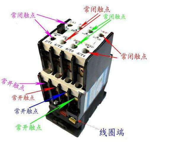
Conventional L1, L2, L3 are phase A, B, and C power supply lines;
Conventional T1, T2, T3 are phase A, B, and C power outlets;
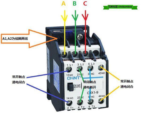
A1 and A2 are the two ends of the contactor coil; there are two A2s for the convenience of the manufacturer. A2 has two connection points, which are the same. When wiring, A1 and A2 can be connected to the contactor side or the contactor. Both sides
13NO, 14NO are normally closed contacts;
Popular science:
NC and NO are auxiliary contacts, NC is normally closed and NO is normally open. NO and NC contact numbers are regular. 11 and 12 are a pair of normally closed points, 13 and 14 are a pair of normally open points, 21 and 22 are a pair of normally closed points, 23 and 24 are a pair of normally open points, and so on, where there are 2 points, All are normally closed, and 4 are normally open. The even number is the terminal, and the odd number is the public;